Подскажите, пожалуйста, может кто знает.
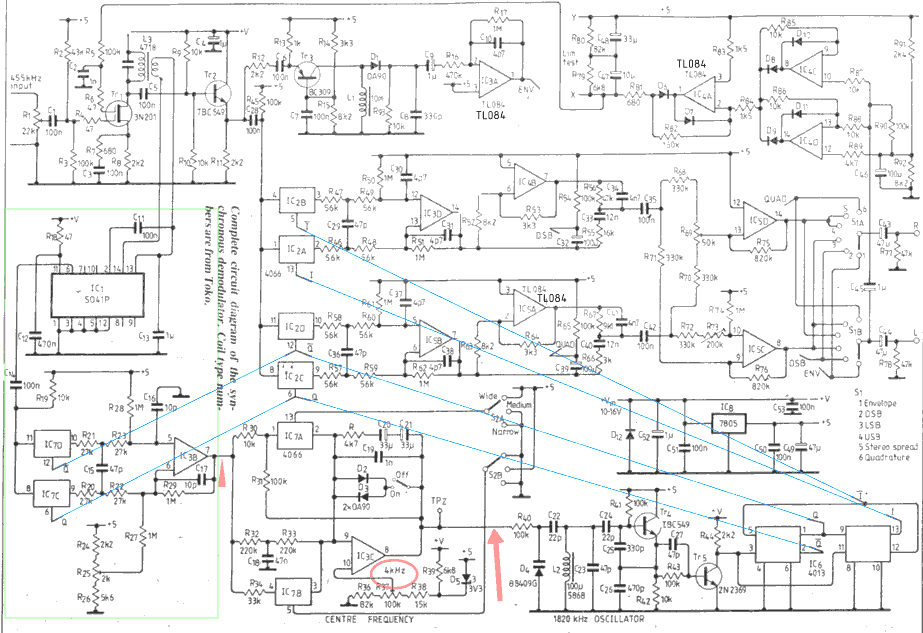
Никак не могу до конца разобраться в работе синхронного детектора (первого, исп. в бытовых приёмниках). Схема ниже и статья (1987г) на английском:

Intermediate frequency of 455kHz en-ters via the input control, R1, which allows the gain to be set to suit the level coming from the receiver so that a 100% modulated signal with full carrier does not quite activate the audio limiter. Transistor Tr, provides buffering and amplification, an output tuned circuit rejecting harmonics of 455kHz. The SO41P high-performance limiter pos-sesses low AM-to-PM conversion and good limiting action down to very low input levels its squared output feeding the balanced modulator formed by 1C7C.D AND 1C3B. A preset, R25, allows offsets to be cancelled so that the re-generated carrier is accurately in phase.
The op-amp IC3C, with 1C7A and IC7B, forms the main loop filter which can be switched between three different bandwidth characteristics. "Wide" allows the loop to lock quickly over a range of ±6kHz and can be used for general tuning around. "Medium" re-stricts the rapid locking range to ± 1 kHz, which is about as narrow as one can go when receiving PM data systems carried on certain broadcast stations: France 162kHz, East Germany 177kHz, UK 198kHz, West Germany 1017kHz. Whatever kind of demodulator is used, the presence of such phase modulation on an AM signal does unavoidably lead to some further degradation of recep-tion in the presence of selective fading or co-channel interference. "Narrow" brings the bandwidth down to ±30Hz. which is low enough to avoid disruption by audio components and still allow some margin for drift and microphony of the receiver local oscillator. This position gives a flywheeling effect, so that the regenerated carrier will not attempt to follow the rapid phase changes and polarity inversions of a signal suffering selective fading or can-cellation fading, where two stations are nearly on the same frequency.
The "Window" selector switch restricts the voltage swing fed to the varicap. D4, and thus prevents the loop being captured by signals away from the desired frequency set by the centre frequency control. This facility means that the receiver IF filters can be ex-ploited to the maximum advantage, in addition to the sideband selection on the unit. For instance, the receiver IF filter could be positioned entirely over one sideband of an AM signal, the appropriate sideband selected on the unit and centre frequency offset to where the carrier now lies. The window facility allows the loop to hold lock tenaciously even when the wanted car-rier is down the slope of the IF filter or buried beneath noise and interference. In the absence of any steady carrier within 30Hz. the loop will generate a carrier stable enough to permit recep-tion of CW, FSK or suppressed-carrier SSB signals.
The output from the loop amplifier is fed to the varicap, D4, which controls the frequency of the Colpitts oscillator formed by Tr4 at 1820kHz. Transistor Tr5 is a high slew-rate amplifier feeding the divide-by-four circuit, IC6 which produces in-phase and quadrature feeds of both polarities at 455kHz to drive the balanced modulator and demodulators. From Tr,, the 455kHz IF passes through an emitter-follower buffer, Tr2, and then to the in-phase demodulator, IC2AB AND IC3D, the quadrature de-modulator. IC2CD and IC5b and the low-distortion envelope detector, Tr, driving D1 with constant current. Op-amp 1C3A amplifies the output from the envelope detector, while IC4B and 1C5A respectively invert and reduce the am-plitude of the in-phase and quadrature demodulator outputs and provide drive for the broadband audio phase-shift networks. The outputs from these net-works are summed by ICSD for USB and differenced by IC5C- for LSB.
Switch S1 selects .the outputs desired. Op-amps 1C4C,D form a full-wave peak rectifier which senses the peak audio output level beyond a threshold of +O.5dBм., giving a small guard band beyond the OdB. output for a full-carrier, 100% modulated signal. The output is amplified by IC4A, which drives the storage capacitors through R81, chosen to give an attack time of a few milliseconds. The double time-constant arrangement allows a short burst of audio beyond the threshold to reduce the gain for only a short time, while longer-lasting high levels will cause a slower release time. These char-acteristics avoid impulsive interference or programme material causing un-pleasant pumping effects. The DC out-put from the time constants is fed to Tr1 where it controls the 455kHz input-amplifier gain.
The unit requires a positive supply between 10V and 16V at 50mA and IC8 generates an internal 5V regulated line; a suitable supply can often be obtained from the associated receiver. Audio outputs may be fed into any stereo system, or just the left output used with a mono amplifier or fed back into the receiver's own amplifier and loud-speaker.
--------------------------------------------------------------------
Насколько я понял, участок спектра, вырезанный фильтром ПЧ поступает на вход ограничителя S041P, там та несущая, которая имеет наибольшую амлитуду ограничивается по амплитуде и далее поступает на балансный модулятор, далее идёт ограничение по девиации несущей (широкая, узкая, средняя полоса). Потом сигнал передаётся на варикап генератора, формирующего ФАПЧ, который работает на 4-й гармонике ПЧ (455*4=1820). Этот генератор управляет триггером, который в свою очередь управляет мультиплексорами, в т.ч. мулитиплексором входа петли ФАПЧ и мулитьплексорами детекторов.
Вопросы
1. Какой сигнал идёт после ограничителя, меандр?
2. Что получается после балансного модулятора (первая слева красная стрелка на рисунке), и почему после ограничения полосы на выходе опрационного усилителя подписано 4 кГц (обведено красным)?
3. Какой сигнал, какая частота потом управляет варикапом генератора, и почему последний работает именно на 4-й гармонике сигнала ПЧ?
4. Каким образом организована ФАПЧ с помощью мультиплексоров, принцип?
5. Схемы демодуляторов для квадратуры (QUARD) и ОБП АМ (DSB) практически ничем не отличаются (вплоть до номиналов!), что тогда вообще здесь понимается под квадратурой?
Мне нужно суметь смоделировать работу этих всех блоков в Block Diagram (курсовая).
Подскажите, пожалуйста, кто что сможет, по работе этой схемы, по любому из её узлов.
Кто что скажет?

